Running Simu5G as a network emulator
Running Simu5G as a network emulator means that the simulation must run in real time and must be able to communicate with the real world, i.e. capturing/injecting packets from/to real networks. This is especially useful for integrating Simu5G with external real-world applications and frameworks. For example, it allows one to make Simu5G interoperable with the Intel OpenNESS framework.
Check out our PIMRC 2020 paper on this topic:
- G. Nardini, G. Stea, A. Virdis, D. Sabella, P. Thakkar, "Using Simu5G as a Realtime Network Emulator to Test MEC Apps in an End-To-End 5G Testbed", PiMRC 2020, London, UK, 1-3 September 2020
An emulation demo
With reference to the video below, the "sender" PC on the left sends 2.5kB packets to the "receiver" laptop on the right every 100ms, and the PC in the middle runs Simu5G as an emulator, transporting packets between the two endpoints. On receipt of a packet, the receiver sends back an ACK. TCP is used as a transport protocol. The scenario emulated in Simu5G is displayed on the middle screen, and it contains one UE (the red dot) that moves away from its serving gNB (the triangle in the central hexagon) and back again. Neighboring gNBs interfere on the downlink spectrum. The deployment bandwdith is kept artificially low, to saturate the radio frame. Within Simu5G, the sender is connected to a remote server (not shown in the picture) and the receiver is connected to the moving UE. The sender screen displays a moving-window average of the round-trip time (RTT) of the communication, measured at the application layer. The RTT climbs up as the UE moves away from the gNB, because its CQI goes down, hence more radio resources are used for the same transmission, and then it climbs down again as the UE moves back towards the gNB. Local delay spikes can be observed, corresponding to H-ARQ retransmissions.
Large-scale real-time emulation with Simu5G
Real-time emulation with Simu5G is possible thanks to:
- the capabilities of the OMNeT++ environment to run a real-time event scheduler;
- the capabilities of the INET library to exchange packets between a running simulation and the operating system.
We distinguish between foreground (FG) and background (BG) UEs, depending on their role within a simulation experiment. A FG UE is one whose application packets and/or statistics you will want to observe. In a FG UE, all the protocols must be modeled (from the application to the PHY sublayer of the NR stack), and PHY-layer reporting must be enabled. On the other hand, a BG UE needs not have the full protocol stack and exists only for the sake of creating resource contention at the MAC level and interference. Thus, a BG UE basically consists of a traffic generator and a mobility model.
Similarly, we distinguish FG and BG cells. A FG cell is one to which at least one FG UE is associated, whereas a BG cell only serves BG UEs. BG cells are employed to create interference to FG cells.
A FG cell needs to perform all the operations required by all the layers of the protocol stack including scheduling in both the DL and the UL directions. On the other hand, a BG cell does not need to implement the whole protocol stack and only needs to determine which BG UEs occupies which RBs at the MAC layer. Since the only tangible effect of BG UEs in both FG and BG’s MAC layers is to affect the scheduling process at the gNB itself, we choose to deploy them using a new module called BackgroundTrafficGenerator within both FG and BG cells.
The figure below depicts the enhanced internal architecture of the NR NIC of a FG cell and the new BackgroundCell model for the BG cell, both including a BackgroundTrafficGenerator submodule.
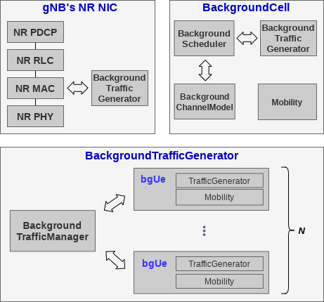 The BackgroundTrafficGenerator includes:
- a vector of modules representing a configurable number of BG UEs;
- a BackgroundTrafficManager module that manages the interaction between the BG UEs and the gNB’s protocol stack.
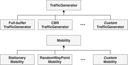
In turn, each BG UE is composed of two submodules, namely Mobility and TrafficGenerator. The former stores the position of the BG UE in the network floorplan and manages its movement, whereas the latter stores the size of the BG UE’s data buffer according to some traffic generation pattern. Both Mobility and TrafficGenerator can be extended through inheritance of OMNeT++ modules to configure the desired mobility pattern and traffic generation distribution, as shown in the figure below.
As far as the BackgroundCell module is concerned, the BackgroundTrafficGenerator submodule described above represents BG UEs under the control of such BG cell. Then, a module called BackgroundScheduler takes care of allocating RBs in both UL and DL directions. To accomplish that, it interacts with the BackgroundTrafficGenerator to get the BG UEs’ buffers and stores data structures relevant to the resource allocation. Moreover, the BackgroundCellChannelModel deals with the computation of SINR for the BG UEs according to the configurable parameters provided by this module (e.g. carrier frequency, transmission power and so on), whereas the Mobility module stores the position of the BG cell in the floorplan. Using this model, one can deploy the desired number of BG cells in the floorplan and each of them can be configured with its own channel model parameters and BG UEs.
Running an emulation example with Simu5G
NOTE: emulation support has been introduced since Simu5G 1.2.0. As per INET instructions, emulation is only available on Linux OS.
The Simu5G repository comes with three (single-machine) emulation examples, which can be used as a basis to develop your own emulation testbed. You can find the examples in the following folders:
- "emulation/extserver"
- "emulation/extclientserver"
- "emulation/extclientserver_bgTraffic"
Description and instructions for the examples can be found in the README files included in the above folders.
Configuring the emulated scenario
In the following, we refer to the scenario included in the "emulation/extclientserver_bgTraffic" folder. The corresponding network is depicted in the figure below:
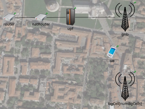
In this example the network consists of one UE connected to one gNB, one UPF, one NAT router, one router, one external (real) server and one external (real) client. The external client application (i.e. associated to the UE in the emulation) sends 10MB using TCP to the external server application, traversing the emulated 5G network. The 5G network includes a (configurable) number of background cells and background UEs. IP addresses and routing tables are set up by using mrt files (see "routing_files" folder).
The interaction with the real world occurs via two INET’s ExtLowerEthernetInterface modules included into the ue and router modules. Such interfaces can receive real packets by network interface cards attached to them. In our case, such network interfaces are created as Virtual Ethernets (veth). Data packets directed to the simulator are routed to the relative veth attached to the ExtLowerEthernetInterface modules. Since all the applications run in the same host, the natRouter module is used to bypass the host operating system and steer the traffic towards the simulator. This way, both real applications send packet to the IP addresses of the natRouter, which in turn performs Network Address Translation by changing the destination addresses to the proper real application’s addresses. The INI configuration for the natRouter router is:
############## natRouter configuration ##############
*.natRouter.ipv4.natTable.config = xml("<config> \
        <entry type='prerouting' \
            packetDataFilter='*Ipv4Header and destAddress=~10.0.2.1' \
            srcAddress='10.0.3.2' destAddress='192.168.2.2'/> \
        <entry type='prerouting' \
            packetDataFilter='*Ipv4Header and destAddress=~10.0.3.2' \
            srcAddress='10.0.2.1' destAddress='192.168.3.2'/> \
        </config>")
IP addresses 10.0.2.1 and 10.0.3.2 are the addresses of the left and right natRouter interfaces, respectively.
Finally, the INI configuration of the ExtLowerEthernetInterface modules to allow the communication with the real world is:
############## Ext Interface configuration ##############
# equip the router with an External Ethernet interface
*.router.numEthInterfaces = 1
*.router.eth[0].typename = "ExtLowerEthernetInterface"
*.router.eth[0].device = "veth0"

*.ue.numEthInterfaces = 1
*.ue.eth[0].typename = "ExtLowerEthernetInterface"
*.ue.eth[0].device = "veth2"
*.ue.extHostAddress = "192.168.3.2"
*.ue.ipv4.forwarding = true
Configuring the OS environment
Once the Simu5G environment is configured, the OS of the host running all the applications must be configured too. The following commands refers to a host equipped with Linux Ubuntu 20.04 OS. veth interfaces are created through the command:
ip link add veth0 type veth peer name veth1
ip link add veth2 type veth peer name veth3
After the interfaces have been created, we assign an IP address to them and enable them by:
ip addr add 192.168.2.2 dev veth1
ip addr add 192.168.3.2 dev veth3
and
ip link set veth0 up
ip link set veth1 up
ip link set veth2 up
ip link set veth3 up
Finally, routes to forward the packets within the simulator and its modules have to be added. In particular, packets must reach the Device app, the natRouter and the MEC platform modules:
route add -net 192.168.2.0 netmask 255.255.255.0 dev veth1
route add -net 192.168.3.0 netmask 255.255.255.0 dev veth3
route add -net 10.0.2.0 netmask 255.255.255.0 dev veth3
route add -net 10.0.3.0 netmask 255.255.255.0 dev veth1
Building Simu5G for real-time emulation
- Make sure that the emulation feature is enabled in the INET project.
- via the IDE: right-click on the 'inet' folder in the Project Explorer -> Properties;
select OMNeT++ -> Project Features;
tick the box "Network emulation support".
- via the command line: in the root INET folder, type 'opp_featuretool enable NetworkEmulationSupport'.
If the feature was disabled, recompile INET with the command 'make' (in the root INET folder).
- In order to be able to send/receive packets through sockets, set the application permissions:
sudo setcap cap_net_raw,cap_net_admin=eip path/to/opp_run
sudo setcap cap_net_raw,cap_net_admin=eip path/to/opp_run_dbg
sudo setcap cap_net_raw,cap_net_admin=eip path/to/opp_run_release
- Compile Simu5G from the command line by running (in the root Simu5G folder):
$ . setenv
$ make makefiles
$ make
Running the emulation
- Run the receiver application, e.g. by typing the command:
./emulation_receiver -p udp
- Run the simulation by launching:
./run.sh -r <RUN_NUMBER>
where:
RUN_NUMBER=0 --> 3 background cells
RUN_NUMBER=1 --> 6 background cells
RUN_NUMBER=2 --> 9 background cells
- Run the sender application, e.g. by typing the command:
./emulation_sender -h 10.0.2.1 -p udp -s 1000 -t 1 -d 60 -o test
where:
-h specifies the address of the NAT router
-p specifies the L4 protocol
-s is the size of application messages
-t is the sending interval
-d is the total duration of the application
-o specifies the output subfolder in folder "stats"
- via the IDE: right-click on the 'inet' folder in the Project Explorer -> Properties; select OMNeT++ -> Project Features; tick the box "Network emulation support".
- via the command line: in the root INET folder, type 'opp_featuretool enable NetworkEmulationSupport'.
sudo setcap cap_net_raw,cap_net_admin=eip path/to/opp_run
sudo setcap cap_net_raw,cap_net_admin=eip path/to/opp_run_dbg
sudo setcap cap_net_raw,cap_net_admin=eip path/to/opp_run_release
$ . setenv
$ make makefiles
$ make
- Run the receiver application, e.g. by typing the command:
./emulation_receiver -p udp - Run the simulation by launching:
./run.sh -r <RUN_NUMBER>where:
RUN_NUMBER=0 --> 3 background cells
RUN_NUMBER=1 --> 6 background cells
RUN_NUMBER=2 --> 9 background cells
- Run the sender application, e.g. by typing the command:
./emulation_sender -h 10.0.2.1 -p udp -s 1000 -t 1 -d 60 -o testwhere:
-h specifies the address of the NAT router
-p specifies the L4 protocol
-s is the size of application messages
-t is the sending interval
-d is the total duration of the application
-o specifies the output subfolder in folder "stats"
Back to Guides